
|
 |

|
|
TECHNICAL BACKGROUND GoalArt is based on multilevel flow models, (MFM). These are graphical models of goals and functions of technical processes. The goals describe the purposes of a system and its subsystems, and the functions describe the system's abilities in terms of flows of mass, energy, and information. MFM also describes the relations between the goals and the functions that achieve those goals, and between functions and the subgoals, which provide conditions for these functions. MFM was invented by Morten Lind at the Technical University of Denmark, see Lind (1990). Several new algorithms and implementations were contributed by Jan Eric Larsson at Lund University, see Larsson (1992, 1994, 1996). BASICS OF MFM MFM is a graphically represented, formal modeling language, in which the intentional properties of a technical system are described. The purposes of the system and its subsystems are modeled with goals. The capabilities of the systems are modeled with flow functions, connected into flow paths. The main functions are sources, transports, storages, balances, barriers, and sinks, and they describe either mass or energy flows. Observers, decision makers, and actors describe information flows. Each flow network can be connected to one or several goals via achieve relations, which means that the functions in the network achieve the fulfillment of the goal. A goal may be connected to one or several functions via condition relations, meaning that the goal is a condition for the function. For a full description of MFM, see Larsson (1992, 1994, 1996) or Lind (1990). The symbols of the MFM graphical language are shown in Figure 1. 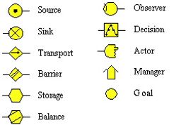 Figure 1. The symbols for different MFM objects. AN EXAMPLE OF AN MFM MODEL The nature of MFM models is probably best explained by an example. We will use a part of the main circulation system of a nuclear power plant. A much simplified process graph is shown in Figure 2. 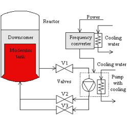 Figure 2. The main recirculation system of a nuclear power plant, (simplified). In this system, reactor tank water flows from a downcomer, via the valve V1, to a pump. After the pump, the water flows through the two parallel valves V2 and V3, back to the moderator tank. The pump is cooled by water. There is also a need for a frequency converter for the power to the pump, since the pump is frequency-controlled. Finally, the frequency converter must also be cooled. The purpose of the main water circulation is to control (moderate) the flow of neutrons in the reactor, and to cool it at the same time. An MFM model of this system is shown in Figure 3. 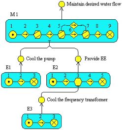 Figure 3. An MFM model of the (simplified) main recirculation system. In the MFM model, there are four flows. The flow network M1 describes the water flow from the downcomer to the moderator tank. The network E1 describes the transport of thermal energy from the pump to the cooling water. The network E2 describes the flow of electrical energy from the supply, via the frequency transformer, to the pump. Finally, the network E3 describes the flow of thermal energy from the frequency transformer to the cooling water. Thus, M1 is a model of a mass flow, and E1 to E3 are models of energy flows. It should be noted that MFM describes how different flows enable each other. In the simple example in Figure 3, it can be seen that the cooling water flow E3 is necessary for the proper function of the frequency converter, and that the cooling water flow E1 and the electrical flow E2 are needed to keep the main water flow operating. The control systems used in today's power plants do not incorporate information on such dependencies. 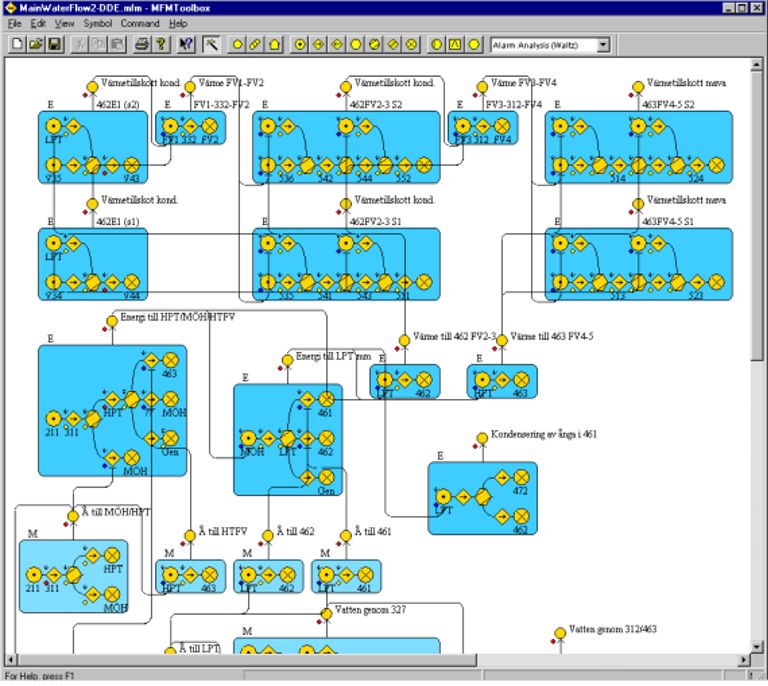 Figure 4. A larger MFM model of the feedwater systems of a power plant. Click to enlarge.
MFM ALGORITHMS Several diagnostic algorithms have been developed with MFM as a basis. The work of Larsson (1992, 1994, 1996) describes algorithms for checking consistency between redundant sensor values, for separating primary and consequential faults in multiple fault situations, fault diagnosis, and generation of explanations in pseudo-natural language. Öhman (1999) presents an algorithm for failure mode analysis. Dahlstrand (1998) presents an algorithm based on fuzzy logic for separating primary and consequential alarms. ADVANTAGES OF MFM  All the algorithms described in Larsson (1996) are based on discrete logic where the "sensor" values are low, normal, or high, and the resulting values are consistent or inconsistent, working or failed, primary or consequential, etc. In other words, MFM uses a linguistic interpretation of logic variables, just as do rule-based expert systems and systems based on fuzzy logic. In addition, the MFM algorithms all operate by searching in fixed graphs. All algorithms can handle the full MFM syntax, including closed loops in both the flows and the means-end dimension, as well as every kind of multiple fault situation. In addition, these complex cases are handled by search methods of linear or sublinear complexity. Together with the discrete logic, explicit means-end concepts, and graphical nature of MFM, this gives several advantages:
The following references give a good overview of MFM research. The best introduction is probably Larsson (1996) for a shorter version, and Larsson (1992) for a comprehensive one. Lind (1990) is the original document outlining both background and the definition of MFM in Lind's version. Dahlstrand, F., "Alarm Analysis with Fuzzy Logic and Multilevel Flow Models," Proceedings of the 18th Annual International Conference of the British Computer Society Special Group on Expert Systems, ES 98, Cambridge, England, pp. 173-188, 1998. Larsson, J. E., Knowledge-Based Methods for Control Systems, Doctor's thesis, TFRT–1040, Department of Automatic Control, Lund Institute of Technology, Lund, 1992. Larsson, J. E., "Diagnostic Reasoning Strategies for Means-End Models," Automatica, vol. 30, no. 5, pp. 775-787, 1994. Larsson, J. E., "Diagnostic Reasoning Based on Explicit Means-End Models," Artificial Intelligence, vol. 80, no. 1, pp. 29-93, 1996. Larsson, J. E., "Diagnostic Reasoning Based on Means-End Models: Experiences and Future Prospects," Knowledge-Based Systems, vol. 15, no. 1-2, pp. 103-110, 2002. Lind, M., "Representing Goals and Functions of Complex Systems — An Introduction to Multilevel Flow Modeling," Technical report, 90–D–38, Institute of Automatic Control Systems, Technical University of Denmark, Lyngby, 1990. Öhman, B., "Failure Mode Analysis Using Multilevel Flow Models," Proceedings of the 5th European Control Conference, Karlsruhe, Germany, 1999. |
||
|
GoalArt, Scheelevägen 17, 223 63 Lund, Sweden, Phone: +46 46 286 4880, Fax: +46 46 286 4882, E-mail: info@goalart.com, Web: www.goalart.com. |